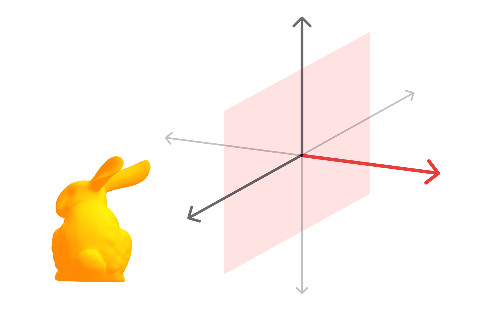
Before you can create anything in 3D, you need to understand how space itself is organized. The 3D coordinate system uses three perpendicular axes, X, Y, and Z, to define the position of every point in a scene. X runs horizontally, Y runs vertically, and Z controls depth, the dimension that makes 3D different from flat 2D design.
Every object in a 3D scene has a position expressed as three values, one for each axis. Moving an object means changing one or more of those values. Rotating it means changing its angle around one of the axes. Scaling it means changing how many units it occupies. These three operations, translate, rotate, and scale, are the building blocks of every 3D workflow.
Not all 3D applications organize these axes the same way. Blender uses a right-handed coordinate system, where Z points up. Unity uses a left-handed system, where Y points up. This difference matters in practice. When designers move assets between tools, objects can flip or rotate unexpectedly because the coordinate conventions differ. Knowing that these two systems exist is the first step to understanding why.
Understanding coordinate systems also means understanding the difference between world space, where objects are measured against the scene's global axes, and local space, where objects are measured against their own internal axes. Grasping this distinction is what makes precise, predictable 3D work possible.
2D Cartesian coordinate system
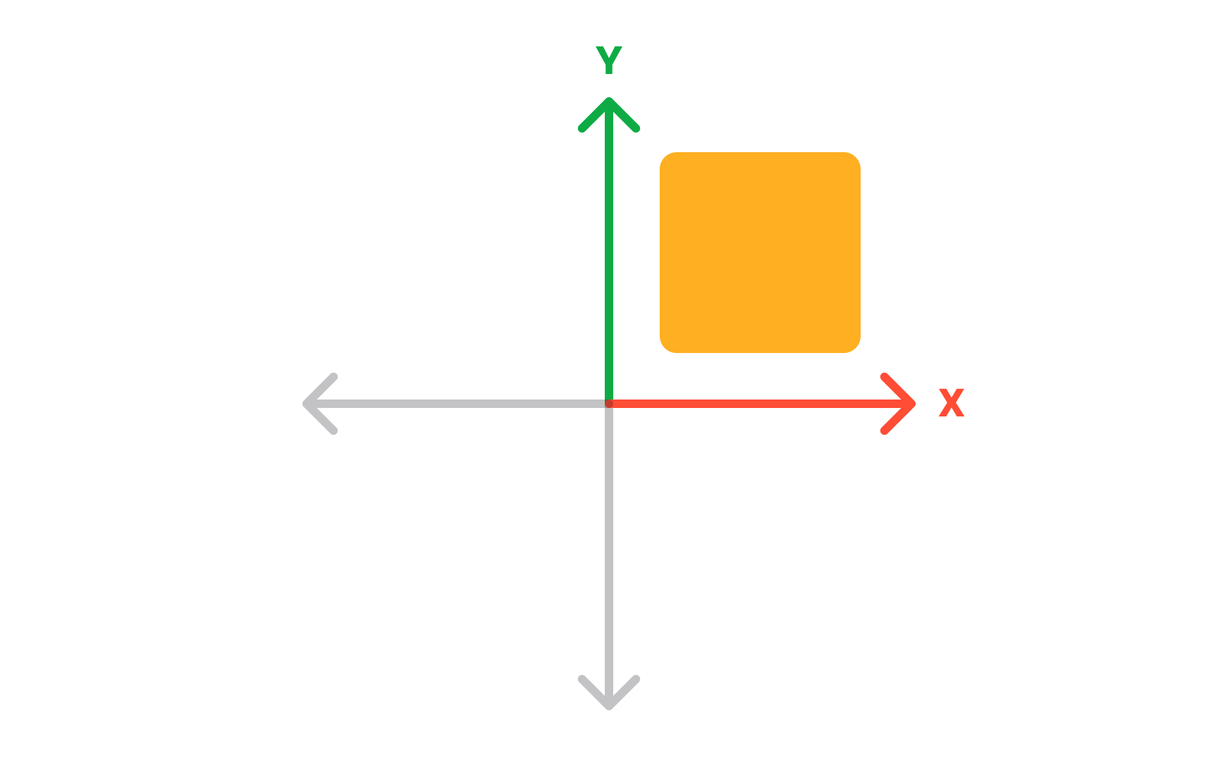
Before working in 3D space, it helps to understand what makes 2D space different. A 2D coordinate system uses 2 axes: X running horizontally and Y running vertically, drawn at right angles on a flat surface. Every point has exactly 2 coordinates, written as (x, y), describing its position relative to where the axes cross. That crossing point is the origin, with a value of (0, 0).
Any location on a flat surface can be described this way. Move right along X, up along Y, and every point has a unique address. This is the same system used in school geometry, spreadsheet grids, and 2D design tools. In Figma, placing a frame at coordinates (200, 100) uses this exact system. The limitation is clear: 2D coordinates describe where something sits on a plane, not where it sits in space.
Understanding 2D coordinates makes the step to 3D more intuitive. The third axis, Z, adds depth to a system designers already know, rather than replacing it entirely. Everything that works in 2D, the origin, the axis directions, the coordinate notation, carries forward into 3D. Only one new dimension is added, but it changes what becomes possible entirely.[1]
3D coordinate system
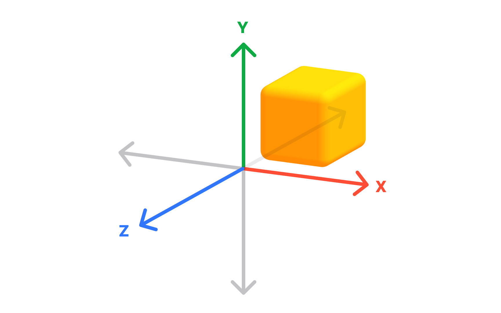
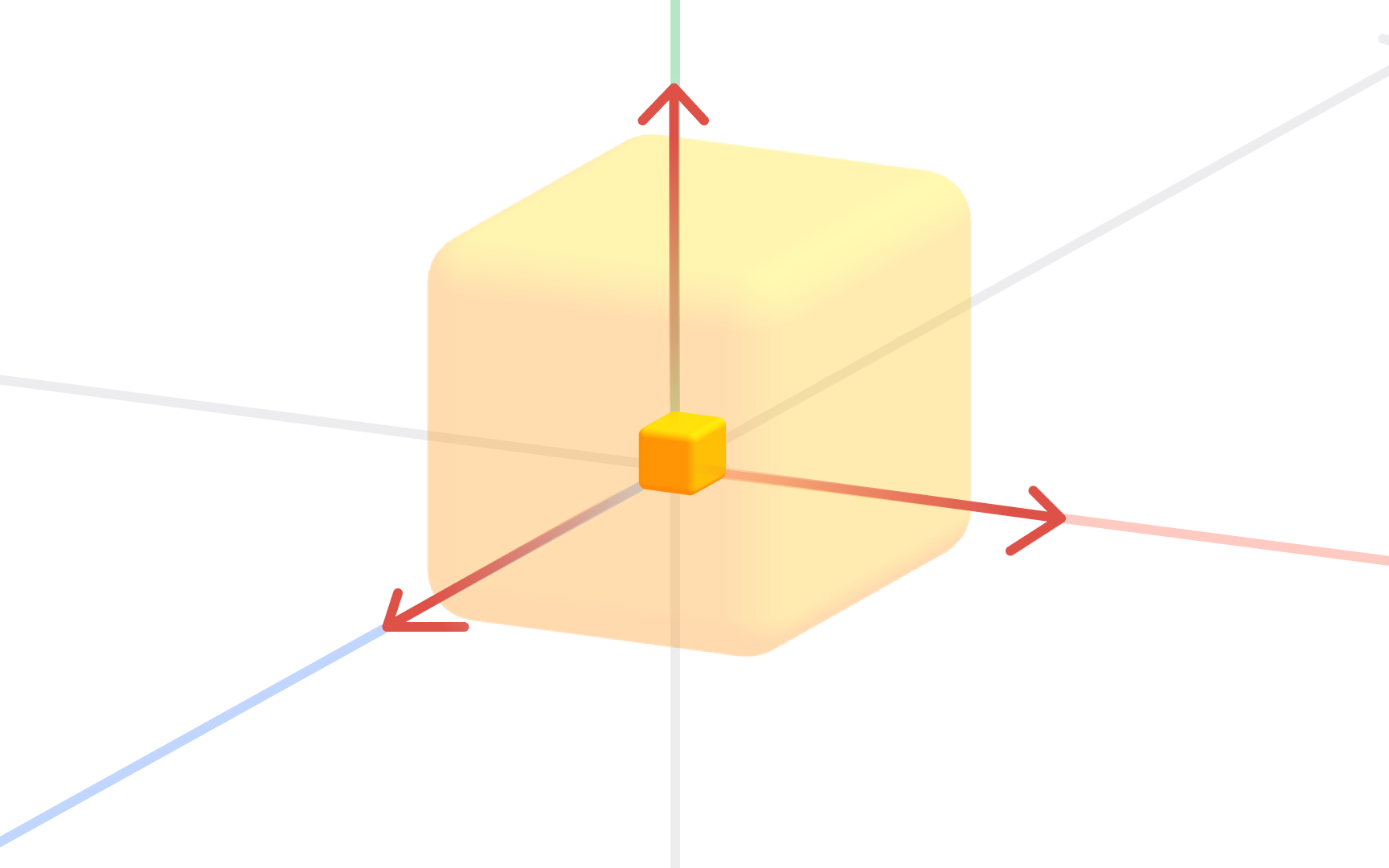
A 3D coordinate system extends the familiar 2D grid by adding a third axis, Z, which represents depth. Three axes, all crossing at the origin (0, 0, 0), describe any position in three-dimensional space. Every point has three coordinates: (x, y, z).
In 2D, a position answers how far left or right and how far up or down. In 3D, a third question is added: how far forward or backward. This is what allows 3D software to place objects in a virtual world rather than on a flat canvas. A cube at coordinates (2, 0, 3) is 2 units along X, at origin height, and 3 units along Z.
Not all 3D tools orient these axes the same way, which matters when moving assets between software. Blender uses a right-handed coordinate system where Z points up. Unity uses a left-handed system where Y points up. Moving a model from Blender to Unity without accounting for this difference often results in assets appearing rotated or flipped. This is one of the most common sources of confusion in professional 3D workflows, and it happens specifically because different tools make different choices about which direction each axis points. Understanding axis orientation early prevents it.[2]
Moving objects with translation
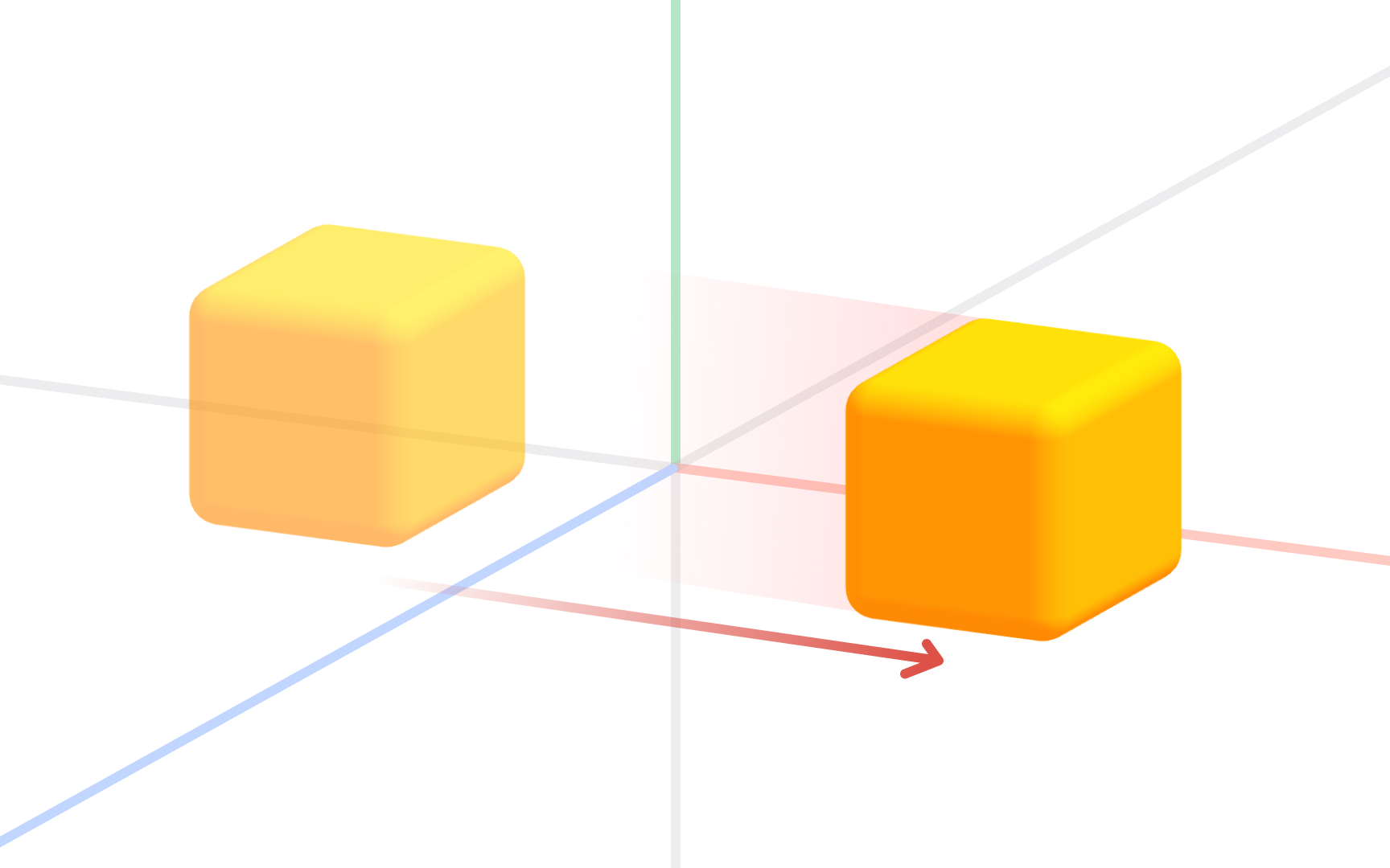
Translation is the most fundamental of the 4 basic 3D transformations. It means moving an object from one position to another without rotating, scaling, or changing its shape. Every point in the object moves the same distance in the same direction, so the form is perfectly preserved.
In 3D software, translation is applied along the X, Y, or Z axis. Moving a chair model 2 units along X shifts it to the right. Moving it along Y raises or lowers it. Moving it along Z pushes it forward or backward in the scene. Most tools allow translation along all 3 axes simultaneously.
For designers, translation is used constantly. Positioning a product in a visualization, placing furniture in an architectural scene, or aligning interface elements in a spatial layout all rely on translation as the primary move. The other 3 transformations each change something about the object's orientation or size. Translation only changes where the object lives in the coordinate system.[3]
Resizing objects with scaling
Scaling changes the size of an object relative to a fixed reference point. Every point moves along a line drawn from that reference, getting closer or farther away depending on the scale factor applied.
The scale factor determines the result. A factor greater than 1 makes the object larger. A factor less than 1 makes it smaller. A factor of 2 doubles the size; 0.5 halves it. A negative factor flips the object to the opposite side of the reference point, producing a mirror image.
Scaling can be uniform across all 3 axes, preserving proportions, or non-uniform along individual axes to stretch in one direction. Stretching a cylinder along Y while keeping X and Z unchanged makes it taller without widening it. This non-uniform scaling is useful for fine-tuning proportions without rebuilding a model.
In design practice, scaling adjusts a model to fit a scene or resizes imported assets to match real-world dimensions. Most 3D tools display scale as multipliers relative to the original size. Keeping track of applied scale matters: a model with a scale of (1, 2, 1) looks correct but has distorted proportions baked in, which causes problems if the model is later animated.[4]
Rotating objects in 3D
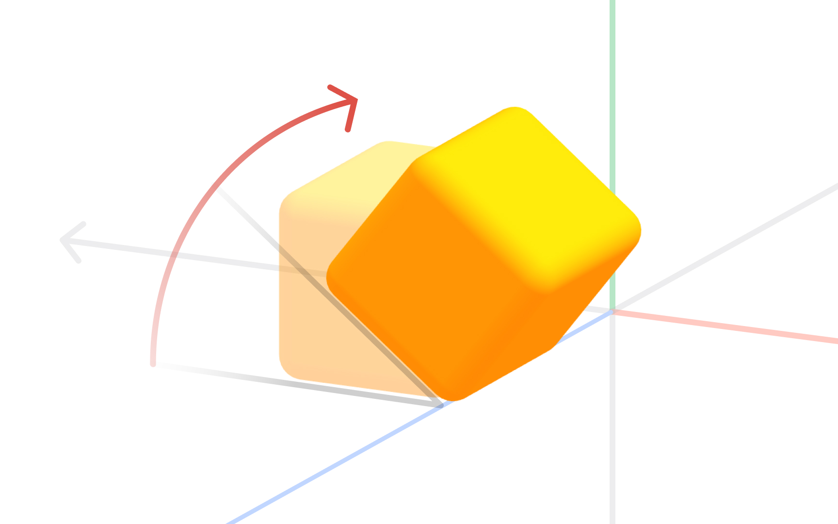
Rotation turns an object around a chosen center point, called the pivot. Every point traces a circular arc around that pivot, and its distance from the pivot stays constant. The object changes orientation without changing shape or size.
Three values define any rotation: the pivot point, the axis of rotation, and the angle. Rotating around Y turns a model left and right. Rotating around X tips it forward or backward. Rotating around Z rolls it sideways.
Direction matters: rotating 90 degrees clockwise produces a different result than 90 degrees counterclockwise. When combining rotations across multiple axes, the order of application affects the final result, which is why advanced 3D tools let designers control rotation order explicitly.
For designers, rotation is essential for placing objects at natural angles, aligning a model to a surface, and animating turns. Combining rotation with translation and scaling covers the full range of basic object manipulation in any 3D environment. Together, these 3 transformations are the foundation of every modeling, product visualization, and spatial design workflow.[5]
Top view in 3D software
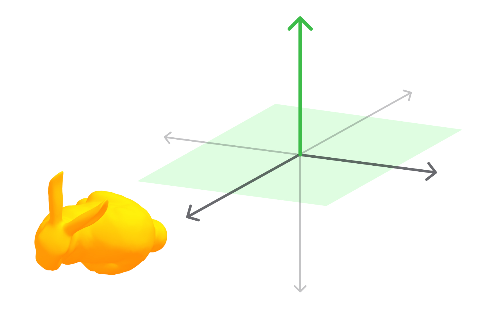
Every 3D modeling tool provides standard orthographic views that show a scene from a fixed direction without perspective distortion. The top view looks straight down along the Z axis onto the XY plane, as if hovering directly above the scene.
Because perspective is removed, the top view shows width and depth at true scale. Objects appear as they actually are, not compressed by distance. This makes it ideal for checking horizontal spacing, aligning objects side by side, or confirming a layout matches a floor plan.
A designer positioning furniture uses a top view to confirm correct spacing before checking height in the front or side view. Product designers verifying component depth in a layered assembly do the same. Top view pairs with front and side views to give a complete, undistorted picture from all 3 perpendicular directions.
Most 3D tools assign keyboard shortcuts to snap to standard orthographic positions. In Blender, numpad 7 jumps to top view. Knowing these shortcuts makes switching between views fast enough to feel natural. Relying only on perspective view leads to misaligned geometry and positioning errors that are hard to catch until rendering.[6]
Front view in 3D software
The front view looks along the Y axis toward the XZ plane, showing the scene from directly in front. Like all orthographic views, it removes perspective distortion, so widths and heights are shown at true scale regardless of object distance.
This view is most useful for checking vertical proportions and horizontal alignment simultaneously. A designer building a character model uses a front view to confirm shoulders are level and the proportions match a reference. An architect uses it to verify facade dimensions before sharing files with a contractor.
The front view has a counterpart: the back view, which looks from the opposite direction. Objects can look quite different from front and back, particularly asymmetrical designs, so checking both catches issues that one direction alone would miss.
One important note is that the axis the front view aligns to varies between applications. Blender defines front view as looking along the negative Y axis at the XZ plane. When moving assets between tools, confirming which direction each application calls "front" prevents importing a model that faces the wrong way, an issue that is easy to miss until the asset is already placed in a scene.[1]
Side view in 3D software
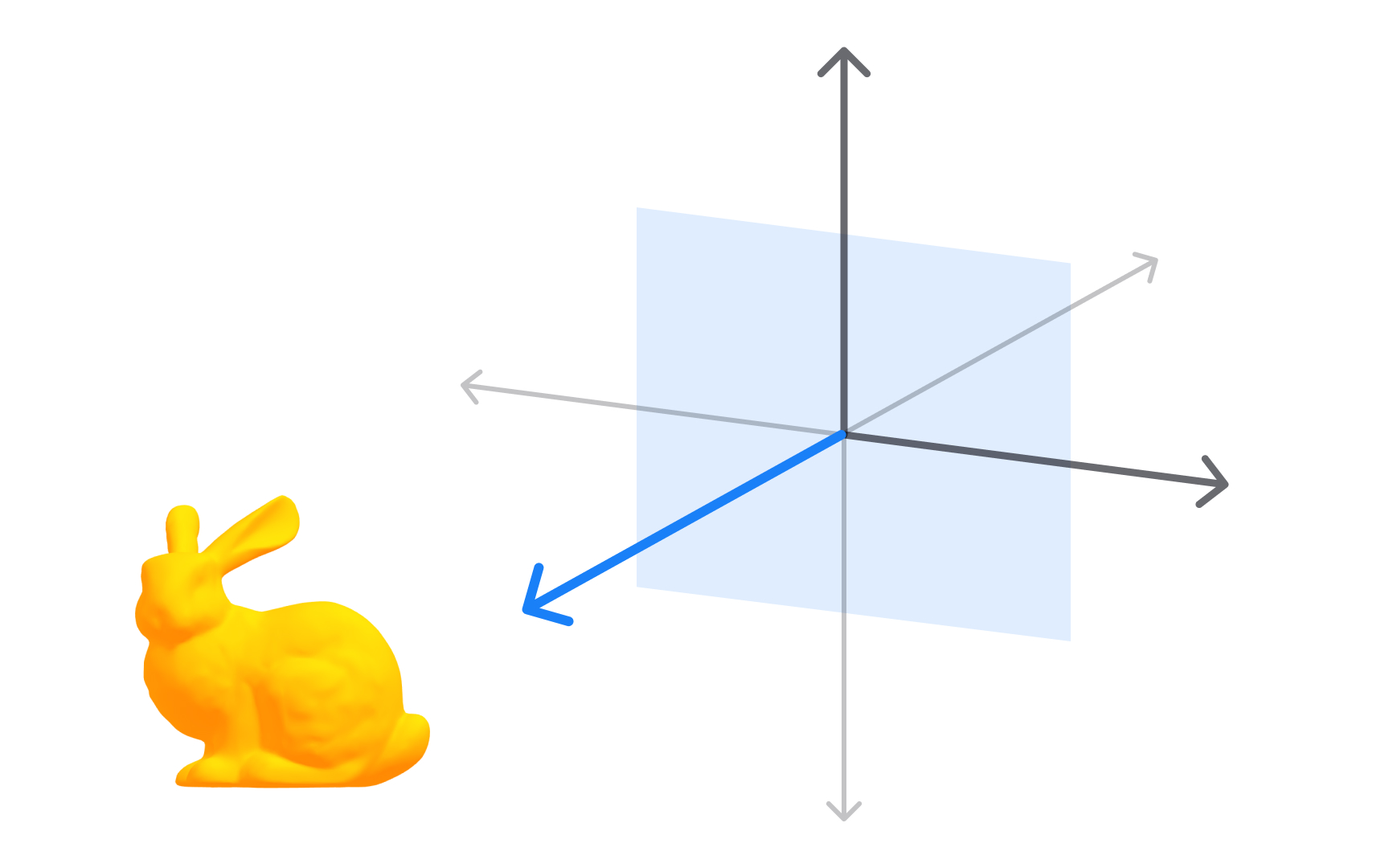
The side view looks along the X axis toward the YZ plane, showing the scene from the left or right. It reveals depth and height together at true scale, making it ideal for checking how objects relate front-to-back in a scene.
In character design, the side view is where silhouette work happens. A designer checking whether a profile reads clearly, whether a nose protrudes enough, or whether a back is correctly curved relies on this view. In product design, it shows whether a device has the right thickness and whether components sit at the correct depth within the housing.
The left and right side views look along the same axis from opposite directions. A model's profiles often differ, particularly for asymmetrical products or characters with detail on one side only. Checking both sides catches issues that appear on one side but are hidden from the other.
Working across top, front, and side views is the 3-view approach, standard in both technical drafting and 3D modeling. Each view shows what the others cannot. Used together, they verify position, proportion, and spatial relationships across all 3 dimensions without relying on a perspective view that can mislead.[7]
Polygonal models
Polygonal modeling is the most widely used method for creating 3D objects in design and production. A polygonal model is built from a mesh of flat 2D shapes, typically triangles or quadrilaterals, connected at their edges to form a surface. Every component of that surface is described by 3 elements: faces, edges, and vertices.
Polygonal models dominate because rendering engines, game engines, and real-time 3D tools all process polygons efficiently. A sphere, a car door, a product enclosure, or a UI element in a spatial interface: all are polygon meshes in the tools designers use daily. Blender, Cinema 4D, Maya, and Spline all use polygonal meshes as the default object type.
The number of polygons determines visual quality and performance cost. More polygons produce smoother curves and finer detail but take more processing power. Fewer polygons are faster but look faceted at close range. Managing this tradeoff is a core skill, particularly for game assets and web 3D.
Understanding faces, edges, and vertices is the foundation for all modeling work. Every operation, whether extruding, beveling, or adding edge loops, acts on one or more of these 3 elements.
Faces of a 3D model
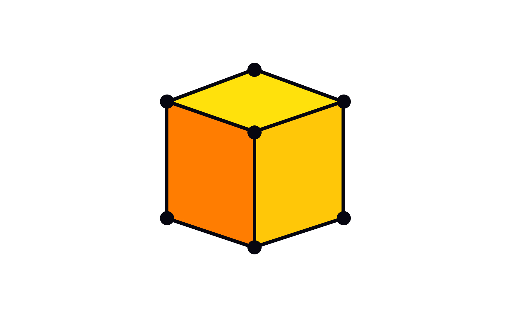
A face is one of the flat surfaces that make up a polygonal 3D model. When a 3D object is rendered or displayed, it is the faces that catch light, hold materials, and form the visible surface. Edges and vertices define structure, while faces define what is seen.
Most 3D models use quadrilateral faces, called quads, with 4 edges and 4 vertices each. Quads are preferred because they deform cleanly during animation and subdivide predictably when smoothed. Triangles, called tris, are used where quads would be awkward, and are required by many game engines that convert all geometry to triangles at runtime. Faces with 5 or more sides, called n-gons, are generally avoided because they can cause shading artifacts under subdivision.
The arrangement of faces across a model is called topology, and it directly affects quality. A product enclosure modeled with clean, even quads will accept smoothing and look polished. The same shape with poorly placed n-gons may develop shading errors under certain lighting. For designers working in 3D, understanding topology is part of the quality standard for production-ready work, not just a concern for specialists.[8]
Vertices of a 3D model
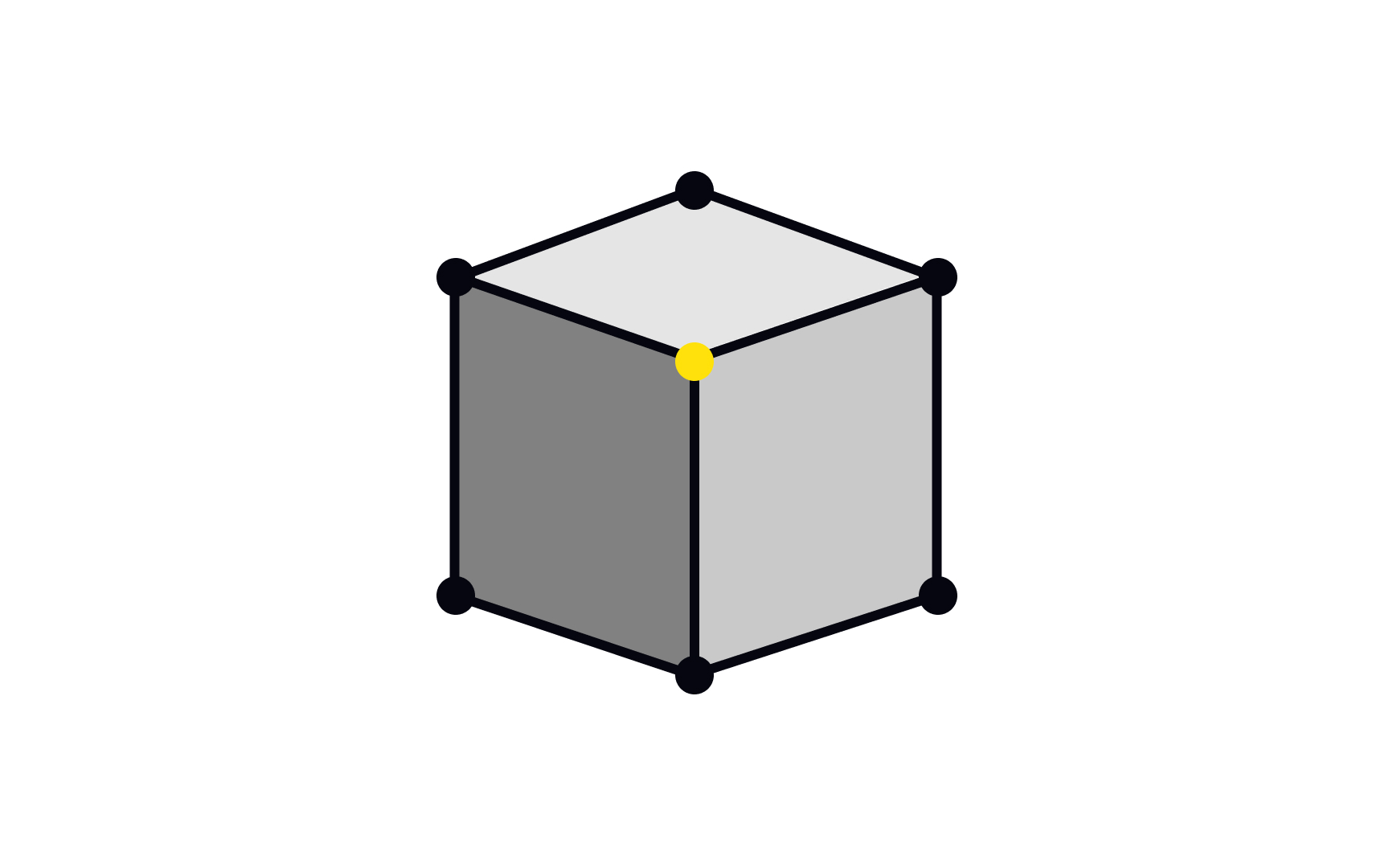
A vertex is a single point in 3D space, defined by its coordinates (x, y, z). In a polygonal mesh, vertices are the corners where edges meet. Every face is bounded by at least 3 vertices, and the position of each vertex determines the shape of the faces around it.
Moving vertices is the most fundamental modeling operation. When a designer adjusts the shape of a mesh, they are selecting and repositioning vertices, individually or in groups. The overall form of a model is determined by where its vertices sit in space.
Vertices carry data beyond position. UV coordinates, which control how textures map onto a surface, are stored at the vertex level. So are vertex normals, which affect how light interacts with the surface. In animation, vertex weights determine how much influence each bone has over each point.
A cube has 8 vertices. A simple sphere subdivided enough to appear smooth might have hundreds. A detailed character model can have tens of thousands. Managing vertex count is part of the same performance discipline as managing polygon count: higher numbers mean more detail but more cost. Decisions about vertex density are part of every professional 3D workflow.[9]
Edges of a 3D model
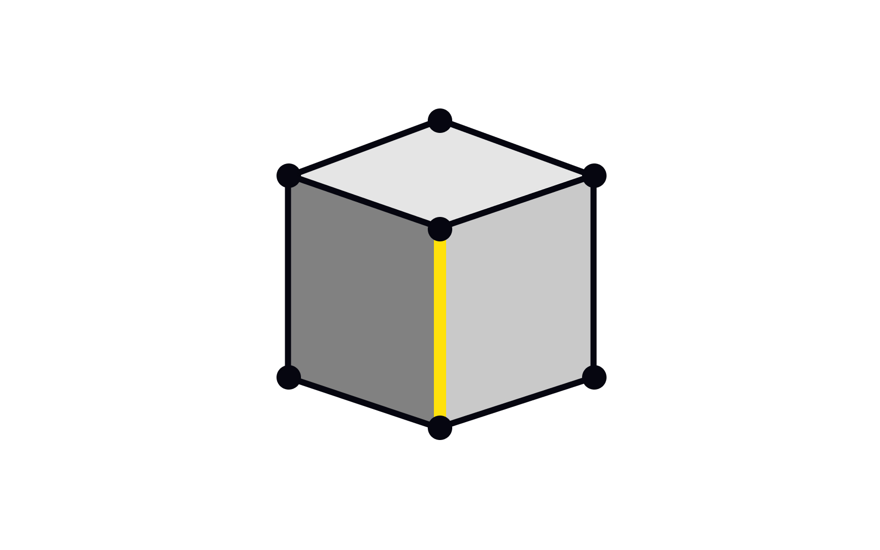
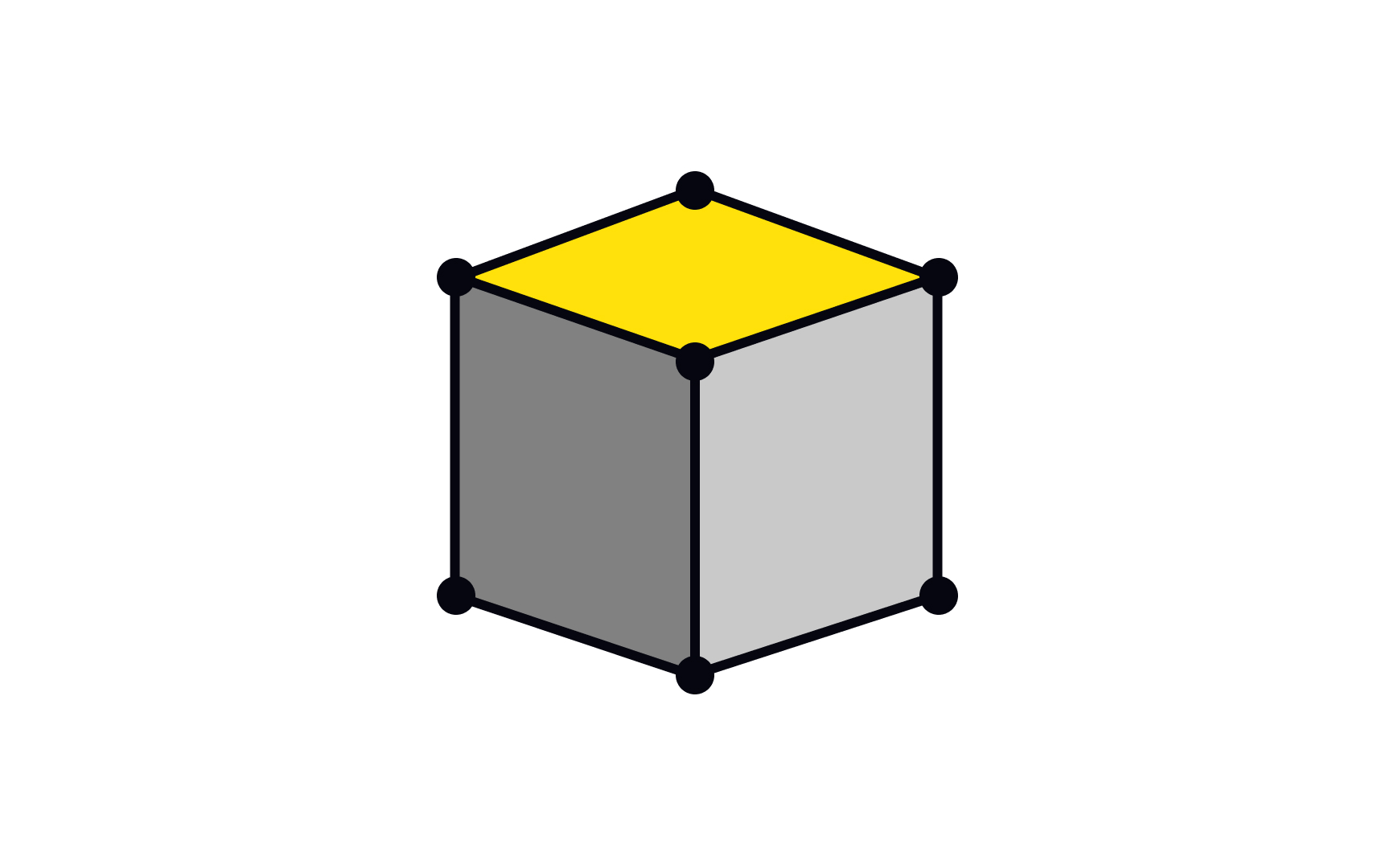
An edge is a straight line connecting 2 vertices in a polygonal mesh. Edges define the boundaries between faces and give the mesh its structure. Every face is enclosed by edges, and each edge is shared by the 2 faces on either side of it, or by just 1 face if it sits on the open boundary of a mesh.
Edges matter most in modeling operations. Beveling an edge rounds off a sharp corner, which is how the chamfers on product casings and device edges are created. Adding an edge loop, a ring of connected edges running around a model, adds local detail without increasing polygon count everywhere. Creasing an edge tells a subdivision modifier to hold it sharp rather than smoothing it away.
The distribution and direction of edges across a model is called edge flow, and it is a quality consideration in production work. Clean edge flow follows the natural contours of the surface and ensures the mesh deforms correctly during animation. Poor edge flow causes shading problems and makes models harder to edit later.
A cube has 12 edges. Understanding what edges do and how to manage them is essential for anyone moving past basic primitives into models that hold up under scrutiny in a real production pipeline.